The generator within a wind turbine is capable of producing up to 5 MW of electricity. An unfortunate side effect of that is that voltage can build up within the generator itself.
That voltage naturally runs to ground, but along that path, the voltage arcs through the bearings within the generator’s rotor.
This constant discharge of high-frequency voltage through the rotor bearings causes microscopic damage that can eventually lead to generator failure, a costly problem to say the least.
“The voltage exists because you drive the generator with a frequency converter, or variable frequency drive,” said Jens Leipner, Electro Static Technology’s Sales Manager, Northern Europe. “That means you couple the voltage inside the rotor. The rotor is inside the generator and is held by two bearings — on the drive inside and on the non-drive inside. This voltage wants to go to the ground, and the only possible path to go to the ground is through the bearings. And if you have high voltage on the rotor, and that wants to transfer to the bearings, then it will have to pass through the balls inside the bearings. And there’s a little grease film inside the bearings, too, just as an insulating part. The voltage grows more and more and sparks through the grease film.”
Micropitting
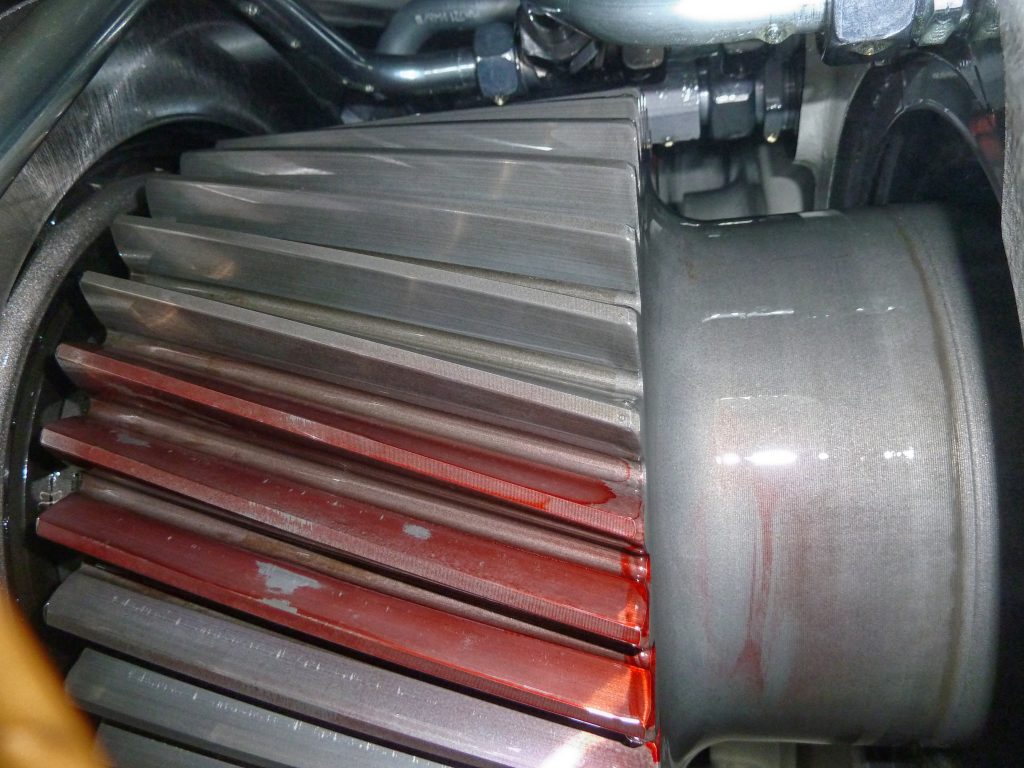
As the voltage arcs through the bearings, microscopic pits begin to form. These pits are the result of high-frequency current running through the oil or grease film, causing a little spark inside, according to Leipner.
“Every spark produces this little pit,” he said. “And the result of this is a washboard pattern surface on the bearing. And the balls in the bearings get very loud and get hot, and then the bearing breaks.”
This voltage can create almost 16,000 pits per second, resulting in a frosted, washboard pattern. As the washboarding becomes more prominent, the bearings begin to make noise, and eventually, they will break, forcing the generator within the turbine to shut down.
“You can imagine the problems that arise in order to pick up this big generator with a big crane, and then it’s so much money to put it on the ground and repair it,” Leipner said.
Sometimes the bearings at the top of a turbine can be changed, but that can also prove difficult since the bearings are about 300 to 400 millimeters in diameter.

Carbon block brushes
In the past, carbon block brushes have been used in grounding systems, but carbon block brushes are insufficient in that they are mainly effective against low-frequency voltage, and they produce a layer on the shaft that looks like a gray patina, which is why the brushes don’t work well for grounding high-frequency voltage.
“It’s a very, very interesting thing,” Leipner said. “I have measured a very big generator with 8 MW where they have installed carbon block brushes on the shaft. They had problems with the gearbox behind this, so they asked us if we could measure this. We measured 40 volts peak-to-peak with the touching carbon block brush on the shaft. So, you can see that the carbon block brush does not work for high-frequency voltage. It was a really interesting measurement.”
Most wind turbines today use doubly inverter-fed induction generators, according to Leipner.
“That means you have a slip ring on the one side to three phases to produce the electrical magnetic field inside the rotor,” he said. “They have three phase rings and one grounding ring. There are also those carbon block brushes running on it. And this is normally for grounding, but remember, the carbon block brushes don’t ground the high-frequency voltage.”
Grounding high-frequency voltage
With technology in place to sufficiently ground the low-frequency voltage, it became necessary to tackle a way to properly ground the high-frequency voltage that could eventually force a major turbine shutdown.
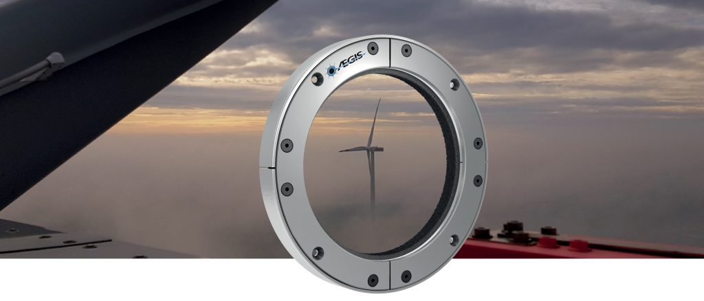
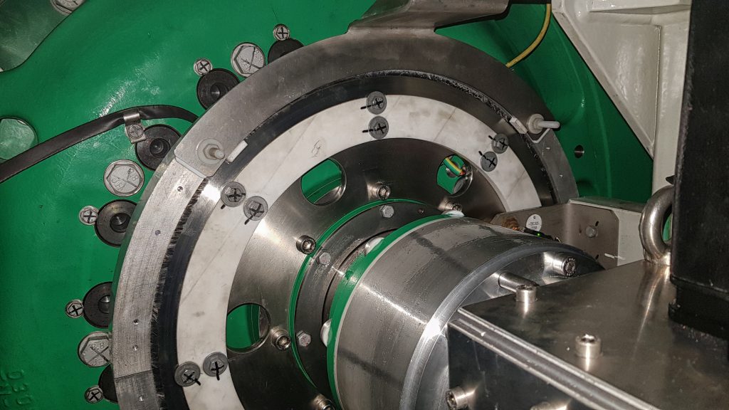
To prevent this from causing potential turbine failures, Electro Static Technology developed the AEGIS® PRO Ring.
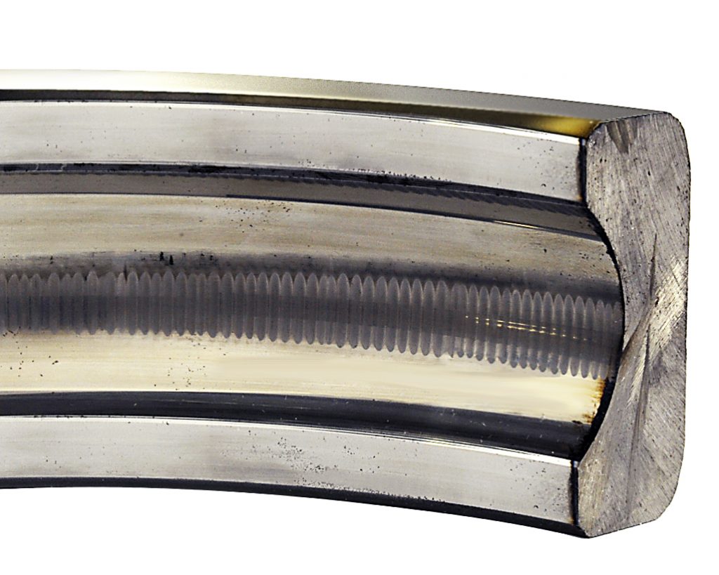
These grounding rings enclose the shaft with hundreds of thousands of conductive microfibers. Because these fibers cover a large surface area, they have a low impedance for high-frequency currents.
The development of the AEGIS® PRO Ring came from work done with printers, where fibers would brush up against a piece of paper to remove the electrostatic charge, according to Leipner.
“This was the development of our ring,” he said. “So, we made a round one that was much more fibrous with special fiber to touch the shaft. That was the beginning of AEGIS® in 2005. Now it’s been on the market nearly 15 years.”
The AEGIS® ring creates a shortcut next to the bearing for the high-frequency voltage to move through.
“The high-frequency voltage on the shaft wants to go through the bearing, but we make a shortcut with our AEGIS® ring,” Leipner said. “Now the high-frequency voltage passes through the AEGIS® ring from the shaft to the fiber and then to the ring and to the ground from the motor.”
For wind turbines, in order to prevent both the low- and high-frequency voltage from damaging the turbine’s parts, a combination of the carbon block brush with the slip ring, along with the AEGIS® ring, is often used, according to Leipner.
The high-frequency voltage can be measured on a running turbine, and Leipner said tests were performed to determine what kind of an effect the high-frequency voltage could have on a running system.
Making a case for AEGIS®
Electro Static Technology performed measurements on a turbine for a generator manufacturer on a 140-meter high turbine with a 135-meter blade diameter with a permanently excited generator with VFD control.
The generator was already equipped with brake disc rollers for low-frequency grounding. It also had shaft grounding in the form of a “violin bow” for high-frequency voltage.
Without any shaft grounding, the high-frequency shaft voltage was a dangerous 20 volts peak-to-peak. With the “violin bow,” the voltage could be reduced to slightly more than 4 volts. Below 5 volts is a safe level for the shaft voltage, but the “violin bow” was experiencing heavy wear because these components are pressed under tension against a spinning shaft. As a result, they can wear through quickly.
Outlasting the life of the bearings
After AEGIS® PRO rings were installed, the residual shaft voltage was reduced to less than 1 volt. Furthermore, since the fibers of the ring are not under tension, they become much more durable than other grounding systems.
“The very good thing is that we have nearly no wear rate on the AEGIS® fiber,” Leipner said. “That means about 0.03 millimeters of wear in 10,000 hours, which translates into 10 to 20 years of running it with no problems.”
With the life of a bearing clocking in at about 10 years, that means an AEGIS® PRO ring can theoretically outlast the bearing that it’s protecting.
“The fibers touching the shaft are very smooth and very soft, so we don’t destroy the shaft or the surface from the slip ring; everything runs freely,” Leipner said. “We say a bearing lifetime normally is 8 or 10 years, but with the AEGIS® PRO ring, if everything is perfect, you can actually use it again.”
Other industries
With the AEGIS® Shaft Grounding Ring’s ability to ground high-frequency voltage, the technology has made its way into many different industries.
“That means motors where you normally have problems with the frequency converter,” Leipner said. “Every motor with a frequency converter has high-frequency shaft voltage that wants to go to the ground. This happens in applications from water treatment to manufacturing to HVAC/R. So, we normally produce these rings for those industries, but also for electric vehicles, ranging from cars to trains.”
The need to ground high-frequency voltage is evident in the success the AEGIS® Shaft Grounding Ring has had within the wind-energy market, according to Leipner.
“The main results of the ring are that they have no wear rate, that you have no maintenance after you install the ring,” he said. “And also, you can see that it’s working. You can see it from the field.”
MORE INFO www.est-aegis.com


