Home Sept/Oct 2009

Sept/Oct 2009

Fastening Technology for Tower Integrity

0

Wind turbines are awe-inspiring machines. Rising hundreds of feet into the sky, with their blades spinning majestically, they make a humming sound that I find pleasant. It seems as though nothing could ever bring them down. Since I admire these structures my thoughts often turn to what keeps them going day after day, diligently doing the duty of creating energy, and it occurs to me that one of those components is fairly easy to identify—fasteners. With the recent attention given to an Ohio-based fastener manufacturer by President Barack Obama, now seems like a good time to re-examine the critical nature of a component that has been dismissed as a “commodity” by too many buyers and engineers in the user community. Power generation from wind depends on bolts, studs, screws, and nuts, from the structural bolting patterns at ground level all the way to the generator high in the air.

An improperly designed joint, a substandard screw, or even a loose nut can bring the entire operation to a stop. It can happen suddenly or take many months, going unnoticed until the final failure occurs. There are three basic elements to a sound joint: good joint design, proper assembly and maintenance of the joint, and consistent high-quality fasteners. Proper joint design is both a science and an art, and the engineer should keep in mind what has worked for similar applications in the past, since the history of wind turbines is relatively brief. Many U.S. manufacturers are putting their components into turbines for the first time, in fact. It may be useful to review the basic steps of bolted joint design. First the basic geometry of the joint should be considered, and the material of the clamped parts. Give thought to the number of axes in the joint, and make the initial selection of joint materials. Second, calculate the magnitude, direction, and introductory point of the external forces acting upon the joint, and whether they are static or dynamic. Determine the acting temperature range of the joint and coefficients of thermal expansion of the mating parts. Next, select the material properties, size, drive style, and thread type of the fastener. Fasteners act like springs in storing energy to resist external forces that work to separate clamped parts. Long, slender screws are the best choice.

A 1:4 or even 1:6 diameter to length ratio is desirable. Estimate the clamp load required for keeping the joint functional. Develop a force diagram, as shown in Fig. 1. Now calculate the mating material’s capacity to resist embedment while keeping in mind other setting force losses. Determine safety factor desirable for the joint. Now, the most important step: test the joint in application under realistic conditions. The second element of a sound joint—proper assembly and maintenance—has new challenges in wind power applications. The forces involved in these applications may differ from those in the original design. Fastener maintenance on a wind turbine will present unusual challenges—working height, space restrictions, and awkwardness of tool use in various weather conditions. This must be dealt with at the design level. Assembly and maintenance of the bolted joint must be realistic. Keep in mind that preload or tension is the goal in maintaining the fasteners. If direct tensioning of screws cannot be achieved, or clamp load indicating devices are not appropriate, then it is good to know about the relationship between torque and tension. Torque and tension have a linear relationship. and it is examined most easily by a brief treatment of the short form torque equation and a review of a study published by the fastener industry outlining various means of tightening screws.

The short form torque equation is: Tin = KxDxP, where Tin is the input torque, K is the nut factor (loosely equivalent to a coefficient of friction), D is the stress area of the screw for inch series parts, or nominal diameter for metric parts, and P is the desired preload. It has been estimated that there are over 250 factors that influence the value of K. Most fastener manufacturers publishing recommended installation torque charts have tested hundreds of their screws to find an average value for K in steel or another specified material and expect a scatter of plus or minus 20 percent. What are a few of those 250-plus factors making up K? Thread fit and condition of the mating threads, the finish on the fasteners and clamped parts, the means of assembly and frequency and means of maintenance, and whether a fastener has been previously installed and in service are just a few. Poor thread fit and condition not only hinders installation, it subtracts from clamp load achievement. Tab. 1

Properly rolled threads on a screw, rerolled to smooth out nicks picked up in processing, assure a consistency in stretching the part to desired preload. Plating or coating screw threads or nut threads changes the relationship between torque and tension. For instance, zinc plating increases friction between the threads, while nickel reduces drag. Organic finishes can be modified to different friction coefficients but care must be taken in choosing organics. The thickness of the coating needed to achieve the corrosion resistance desired can interfere in mating parts if that thickness is not accounted for in the screw design. Torque, when used as a means to achieve tension has variability, stemming from the tools, the operator, and even the conditions at the time of installation.

Fig. 2 shows the variability of preload as a result of using certain means of installation. Other factors influencing clamp load in assembly or maintenance are tightening sequence, initial relaxation of the joint and improper use of mating fastener components. Fasteners lose 5-10 percent of initial clamp load in the first 24 hours after tightening. Screws in a joint should be tightened using two or three snugging passes then a final tightening to desired torque. It should be done in a pattern designed to spread the load equally among the screws and so as not to create prying action felt by any screw. The correct choice of mating fasteners should not be taken lightly. Screws and nuts should be strength matched. Having a nut the same strength as the screw ensures that the nut threads fail first, because they are actually a bit stronger than the screw threads. A failed nut is more easily detected than a broken screw.

Hardened washers should be used when needed under hardened screws and nuts to increase the effective bearing area of the joint. Split lock washers used to prevent loosening under the heads of hardened screws actually hinder the performance of the joint. Conical washers and disc springs can increase the effective length of a screw, allowing it to develop more preload to resist external forces. Reuse of fasteners previously installed can be covered in three words—don’t do it! The relationship between torque and tension assumed during the original installation changes with subsequent reuse. The second time a screw is torqued to the recommended value, the clamp load achieved is reduced. Fastener manufacturers’ recommended installation torque data presumes certain conditions and mating materials that are usually spelled out in the chart. The values are not meant for anything other than new screws in “as received” condition. Most often taken for granted is the third element in a sound joint: consistent, high quality fasteners. Making the correct choice for any application involves more than simply selecting the tensile strength of the fasteners. There are preferred methods of manufacturing for high strength screws. Threads should be rolled and have radiused roots, and the fillet between head and body should also be radiused. The wire chosen should be free from harmful inclusions and properly prepared for the heading process. In extreme fatigue applications screws can have reduced diameter bodies effectively lengthening them. Thread can be rolled after heat treatment for greater strength. Fastener specifications called out should be reviewed before inclusion on a drawing. Too often I hear from engineers that standards are all the same. While much has been done in the past few years to rationalize international standards, differences remain.

Dimensionally ASME, ISO, and JIS standards are very similar and have many overlapping tolerances. Generally they may be considered “functionally” equivalent with regard to dimensions. The same cannot be said in all cases for high strength fasteners when it comes to mechanical properties and permissible discontinuities. For instance, ASTM A574 and A574M, governing inch and metric socket head cap screws, do not permit laps and seams below the pitch diameter of the screw thread. ISO 6157-3 governing high strength socket cap screws for special applications permits certain laps and seams below the pitch line. In effect, the standard allows a manufacturer to produce a screw designed for a tough application to have flaws in the smallest cross sectional area of the screw. Those thread laps and seams are a contributing factor to fastener and joint failure. Socket head cap screws and other high strength threaded products can be made without flaws in this critical area as proven over the last 100 years by many respected screw manufacturers. Proper raw material selection and maintenance of threading dies eliminate most issues. The best screw manufacturers continue to test production pieces every 30 minutes to ensure that the parts being run are defect-free.

Parts are taken from the machine, sectioned, placed in a mount, and then examined microscopically for the absence of thread laps. The cost difference for this benefit—critical to every part of a wind turbine that helps it work—is a matter of pennies per fastener, not dollars. What is the cost of downtime for a turbine, small or large? Couldn’t we estimate it as hundreds, thousands, or even hundreds of thousands of dollars? Finally, regardless of where or how a fastener is used on a wind turbine let me implore you to know your supplier. There are many notable manufacturing companies around the world that test the worthiness of components from outside suppliers regularly, and they purchase only from those who are approved. Fasteners, if not a part of that list of “from approved sources only” components, should be a part of it. Keep a record of the manufacturers’ markings stamped into the fasteners of your approved sources. One example, on a socket head cap screw, is shown in Fig. 3.

It doesn’t make sense to let an inexpensive yet integral piece of a wind turbine be the thing that brings it to a painful halt. Threaded fasteners have held the world together for 500 years. They should never be dismissed as a commodity.


Big Gears for Big Wind

0

New maintenance services and technologies are constantly being introduced into the wind industry, because a primary concern involves the longevity of towers and related component parts. One of the best ways to insure maximum service life, however, is to utilize the best parts available from the very beginning. This is especially true of the gears used to control yaw, pitch, and to outfit the gearbox.

Fig. 1

Those manufactured by the Gould & Eberhardt line of gasher/hobbers have proven over the past 176 years to provide the quality, accuracy, and endurance required by this demanding application. Founded in 1833, Gould & Eberhardt grew into a huge company employing thousands of people, and it made significant contributions to the U.S. military during both world wars. It became one of the old-school, workhorse lines—including Fellows, Gleason, and Barber-Colman, among others—that still inspire reverence among gear-manufacturing professionals. When Rich Piselli—president of R.P. Machine Enterprises, Inc.—found himself with the opportunity to purchase G&E in 2005, he saw the chance to take a respected and well-established name and update it to meet contemporary demands. With years of experience in reconditioning, rebuilding, and retrofitting every type of gear-manufacturing machine available worldwide, he knew he was equipped to bring G&E back to life.

Fig. 2

Long known as the go-to machine for hobbing and gashing large gears, he realized the updated line would have applications in markets such as mining, off-highway, pulp and paper, construction equipment, and especially wind energy. Armed with that knowledge he purchased the company, including its original design plans and forms, and set to work recreating the only American-made machines powerful and accurate enough to cut gears for wind turbines. The investment was substantial, and not only in terms of the original purchase of the G&E line, but also to support the engineering expertise required to update and improve the design. There was also the matter of building a facility in which this work could take place. Although he already had more than 160,000 square feet under roof on the company’s campus in Statesville, North Carolina, he realized that only a custom-designed structure would allow him to realize G&E’s full potential. This led to the construction of a 40,000 square-foot building with a 34-foot ceiling to house the two 20-ton overhead cranes that carry and position the massive parts that, combined, make up these tough, dependable, and versatile machines.

Fig. 3

“These machines are driven by Fanuc controls,” Piselli says, “and in addition to incorporating all the latest technologies we made them stronger and more accurate by beefing up the base and column, which provides the extra rigidity required to cut more aggressively. That rigidity also contributes to the machine’s integrity, because it won’t shake itself apart like a VTL will when used for this purpose. That type of equipment might work for awhile, but they will eventually lose their rigidity, which will severely affect the precision of the part and reduce the machine’s service life.” As for versatility, the G&E machines can be purchased with one or two columns, with the dual-column option allowing gear manufacturers to avoid changeover times of up to two hours by keeping both the internal and external gasher heads mounted and ready to go to work at all times. The heads are interchangeable, as well, so they can be used on either column or exchanged on a single-column unit. High-speed gear gashing is made possible by large-diameter carbide inserted cutters, and powerful heads up to 100 HP have been supplied for internal and external gashing applications. Of the four gasher/hobber models (see sidebar), the 96GH, 120GH, and 160GH can be used to manufacture spur, helical, and worm gears, as well as special profiles on cylindrical parts. Standard equipment includes a Fanuc 18MIB control and gashing software, with software for hobbing available as an option. Machine design features are the base column, slideways, axis, worktable, standard guarding, hydraulics, and lubrication for both the machine and the cutter head/s.

Fig. 4

The list of optional equipment is extensive, with items such as a heavy-duty extended diameter worktable top, rim support, storage stands for both external hob heads and internal gasher heads, and an auger chip removal system for the external head, in addition to chip conveyors. Also available are Vortec-chilled air for the cutter heads, through-the-spindle coolant, a cutter lifting device, chamferring equipment, and robotic gear-tooth induction heat-treat systems, among other options. G&E also manufactures worms and worm gears, with sets for the largest sized from 20” to 78” center distance, and up to 128” worm gear diameter. Full gear inspection is conducted on site. Touring the impressive facility reveals a well-run, coordinated operation, with specialized teams tending to the many different stages of manufacture. Potential customers are welcome, and existing clients often visit to see the machines they’ve purchased in operation. These visitors will see teams of workers lifting cutter heads into place on the columns, while others mount power panels and run the wiring. The company’s engineers are constantly climbing over the massive machines and peering into their inner workings, overseeing operations with the eye toward precision typical of their profession.

Fig. 5

“We’re very transparent in terms of how we go about doing our work,” Piselli says, adding that lead times are generally 8-10 months. “That’s one of the reasons we invite our customers to come for a visit… we want them to see how carefully their machines are built.” The same is true of the rest of the company’s widespread operations, as well. Founded in 1995, R.P. Machine stocks an impressive inventory comprised of nearly every type and make of gear-manufacturing and related equipment imaginable. They are available as-is for spare parts, reconditioned to operating capacity, or remanufactured and retrofitted, in which the machines are updated with CNC controls and all of the latest available technologies. These services apply to any type of gear machine in existence, including older G&E models from 72” up to 240” diameter capacity. This remanufacturing program provides major improvements, with only the large, basic castings being reused—although they are completely remachined and equipped with hardened and group box-type ways. The tables are modified to feature a hyperbaric table, and newly designed slides, ball screws, lift cylinders, electronics, and heads are incorporated according to the customer’s specifications. The money that can be saved by choosing to pursue this option, no matter the type of machine or its make, is substantial, and a one-year warranty on all used equipment is standard. In addition to these activities and services, R.P. Machine also offers a line of vertical turning lathes (VTLs), drilling lathes, and CNC form dressers, made possible by its acquisition of Hoglund Technologies some years back. It has also recently acquired a wind component machine supplier, now renamed as PKM Systems, which is involved in machining blades for 1.5-2.5 megawatt turbines. And new projects are in the works, as well, with the company’s engineers currently designing a five-axis machine for manufacturing hubs for 1.5, 2.5, and 3.5 megawatt wind turbines.

Tab. 1

“The way they’re made now involves many different setups,” he says, “and our new machine will eliminate that.” As for the company’s entry into the wind industry as a major OEM, Piselli says that “we’ve always seen ourselves as ‘the solutions company,’ so we want to be able to provide additional production opportunities for wind-energy manufacturers. As we continue expanding its capabilities, the G&E line provides just such an opportunity.”

Turbines must meet certification requirements

0

Almost all large wind turbines available on the market today have been certified by an international certification body through a comprehensive design evaluation, testing, and quality-manufacturing review process. When these turbines are introduced into the U.S. market they must also satisfy local requirements for items such as structural and electrical permits. As offshore wind plants are developed on the Outer Continental Shelf (OCS), they will also have to meet national requirements set by the U.S. Department of the Interior Minerals Management Services (MMS). Many of these local and national requirements are likely to be compatible with international standards. However, local and national requirements are not likely to capitalize on the detailed design evaluation that has already been successfully completed by an international certification body working closely with the manufacturers.

These reviews dig deeply into the design issues such as safety and function control strategy, load predictions, dynamics, stress analysis, mechanical design, electrical design, and even the foundation designs. The international certification body is also required to review all test data used to verify these designs as well as the manufacturing quality plan, thus providing a much more comprehensive review of the turbine design than a local engineer is likely to accomplish. However, local engineers are far more capable of assessing how a particular design is suited to local structural and electrical requirements or, in the case of offshore turbines on the OCS, the local MMS regulations. For these reasons the AWEA Standards Coordinating Committee (SCC) has authorized a committee to develop a document that will clearly identify typical and specific U.S. national wind turbine design requirements that are compatible with the International Electrotechnical Commission (IEC) requirements.

The committee will make every attempt not to develop new technical requirements, but will capitalize on existing standards, particularly IEC standards. National wind turbine design standards should facilitate compliance verification activities by local inspectors and project developers attempting to permit turbines that have been certified to international standards and could become AWEA standards recognized by the American National Standards Institute (ANSI). Whether or not these standards start as a guideline and mature to full voluntary standards will be decided by the committee/s and ultimately approved by the AWEA SCC through their ANSI approval process. This standards document must be developed with broad representation from all the invested stakeholders. The final product should be a living document that links the U.S. national requirements to international standards (IEC).

It will require input from experts who work with wind turbines, understand U.S. and/or IEC standards, inspect and approve wind plant installations, regulate wind plant installations, install wind plants, or are otherwise invested in the success of the wind industry. On October 27-28, 2009, NREL will host a meeting at the Omni Interlocken in Broomfield, Colorado, to discuss the development of these guidelines with industry experts.

Topics of discussion may include:
• Scope and purpose of document (or documents);
• General organization of the document;
• Approach, including formation of subcommittees to address topics such as electrical requirements, structural requirements, and offshore requirements;
• Appointment of leaders and secretaries for the committee and subcommittees;
• Milestones and target schedules;
• Logistics (net meetings, document logistics, etc).

Although NREL and AWEA hope that a broad representation from all the invested stakeholders will attend this initial meeting, only technically qualified persons will be encouraged to assist in developing the large turbine certification guidelines. The development of the guidelines, which may eventually become AWEA standards, is expected to take a year or more and will entail the review of multiple drafts of a guidelines document.

Plate Rolling for Wind Towers

0

With the available and untapped wind resources in the United States, wind power is all but guaranteed to be a boon to its economy for quite some time to come. This represents a great opportunity for manufacturers of the component parts necessary to build and erect them, such as the towers themselves. Three-roll translating geometry style plate rolls are suitable, as well as the “more efficient than popular four-roll machines” for fashioning the conical plate sections used in the construction of wind towers. The following descriptions and illustrations provide a summary of the details and advantages to using the three-roll plate system for wind tower production.

Plate Infeeding and Alignment
First, the plate is placed on a supporting, motorized rollway and introduced into the three bending rolls (see Fig. 1). The plate is then aligned with the help of two hydraulic side arms. One is positioned on the opposite side of the material infeed, and the other acts as a rollway. Because the plate will become a circular section with a ring shape, the side that will become the small diameter of the cone must possess a smaller amount of curvature.

Therefore, the plate must be aligned at its central axis and fed into the rolls at a slight angle rather than fed parallel to the rolls (Fig. 2). This conical section is where three-roll bending with a variable axis offers an advantage over four-roll bending. The four-roll configuration requires that the material always be presented parallel to the rolls for the entire leading edge to be prebent. If the plate were presented to a four-roll bender at an angle, the corner of the plate would not be prebent. With a three-roll machine with variable axis the material can be presented to the rolls on an angle, rather than parallel to the top roll axis.

First Prebending/Bending
Next, the leading edge of the plate is prebent. The plate is taken through the rolls’ rotation, up to the center of the top and left-side rolls. At the same time the top roll comes down, pressing and bending the plate. The top roll presses the leading edge of the plate, leaving the remaining plate in a horizontal position on the rollaway. To allow the plate to slide, the side rolls must be tilted at the cone angle. The prebending stage is another area in which three-roll bending with variable axis offers an advantage over four-roll bending for wind tower sections. With a three-roll bender, the prebending can be done on the tilted edge of the plate. In contrast, a four-roll machine uses the top and central rolls to pinch the plate, while its side roll lifts the plate to perform the prebending. Because the plate for a wind tower is very long, a bridge crane or exceedingly long “scissor lift” table are needed to lift and reposition the plate.

Once the plate is prebent, it continues its clockwise rotation. The left hydraulic side arm with double articulation supports a medium to large diameter and leads it up to the hydraulic central arm Fig. 3). To get a good bend, the plate should be closed for 80-90 percent of its final diameter during this first cycle. To facilitate and speed up all operations, three-roll benders can be equipped with a control that shows the position of the rolls and the lateral roll’s tilting. The panel helps the operator move the rolls. In addition, it retains memory of the operation so that it can repeat the operation with plates that have the same dimensions. The panel may give other information as well, such as the presence of anomalies or alarms, diagnostics of all electro valves, and monitoring of automatic lubrication.

Second Prebending/Bending
The trailing edge of the plate is prebent in the same manner as the leading edge (Fig. 4). While the plate ends its rotation, the top roll presses on the last section of the plate to prebend it. The lateral rolls are in the same position they were in for the leading edge, just inverted. Next, the plate is closed by rotating it counterclockwise. The two side arms with double articulation and the central arm provide support for the plate.

Calibration/Cone Extraction
This phase is important because it helps the internal plate tensions to stabilize, allowing tighter tolerance and eliminating the need to calibrate the plate again in the machine after it has been welded. During calibration the plate is rotated clockwise once again. Altogether the plate is rotated three times from one side to the other. While bending can be performed in just one step, the plate sometimes can have an inconsistent tolerance because of the different mechanical features of the material and the internal tensions caused by strains. Therefore, either the pipe needs to be reinserted into the machine for recalibration, or there will be a long task of welding the two ends. The cone is complete and extracted from the roll bender. Each step shown helps to describe and illustrate the benefits to the translating geometry, three-roll system being used for wind tower production as well as many other common plate rolling applications.

Conclusion
Sertom is widely recognized as the pioneer of many current engineering technologies used to manufacture plate rolls. One of the more popular of these concepts is the translating geometry style plate roll. This style machine allows you to have the prebending capabilities of a four-roll plate roll, as well as the rolling ability of a double pinch three-roll plate roll, with a wider range of capacity and functionality of both. Sertom has placed many of these systems in wind tower production facilities all over the world. Many of these same facilities have abandoned four-roll style machines in order to incorporate these more versatile translating geometry machines in their production facilities. Until recently the focus of Sertom was more of an international one, but with the popularity of wind tower production, as well as other needs for larger plate rolls, this has shifted to a direct focus of the North American market. A newly formed partnership has been created with Carell Corporation to begin Sertom North America operations and support direct from the United States.

A look at preventive maintenance

0

With the increasing investment into the development of wind farms, preventive maintenance takes on an important role in ensuring the reliability and cost-effectiveness of this energy business. The reliable operation of the drive train requires the preventive maintenance of key components such as generators and gearboxes. The generator is the heart of the windmill power generation system, as it converts mechanical energy to usable electrical energy. A catastrophic failure of the generator will lead to a complete shut down of the windmill for several days, which results in expensive repairs and lost revenues. This can significantly affect the bottom line financial results. Among the several failure modes that may cause generator failure, the most frustrating and time consuming is a premature bearing failure. Although the cost of bearings is a small portion of the generator cost, its premature failure can cause catastrophic equipment damage and expensive downtime. A bearing replacement process in a wind generator is a complex and expensive process as the generator is housed in a nacelle. The typical cost for a bearing replacement in the field for a 1.5 MW wind generator may run in excess of $25,000 to $75,000, depending upon the location and the accessibility to the nacelle.

It has been observed from field experience that improper greasing, misalignment in the drive train, and shaft current are among the major causes of premature bearing failure in generators. There are several different improper greasing practices that occur: under-greasing, over-greasing, or the use of a grease type other than that recommended by the generator manufacturer. Bearing seizure can occur due to lack of lubrication if enough grease is not supplied to the bearings. Over-greasing of bearings may lead to excessive heat generation inside the bearing, which can lead to uneven thermal expansion of rollers and race causing a catastrophic bearing seizure. Some manufacturers supply generators with automatic greasing units to ensure the correct amount of grease is applied. Another common mode of premature bearing failure is Electrical Discharge Machining (EDM), which is caused by a passage of current through the bearings. This damaging flow of current can be prevented by insulating the bearings. Ground brushes are used in conjunction with insulated bearings to safely discharge the potential that otherwise discharges through bearings and damages the bearing insulation. It has been frequently observed from field repair experience that EDM bearing damage is often caused by improper installation or the mechanical wear of the ground brush on the machine.

Premature catastrophic bearing failure can also be caused by a high degree of misalignment between the gearbox and the generator. Misalignment in the coupling between the gearbox and generator leads to additional axial, radial, and angular forces on the generator bearings that reduce the bearing’s life, and in extreme cases results in failure. Implementing robust preventive maintenance programs and installing continuous condition monitoring systems on the generator can help avoiding premature bearing failure modes. A preventive maintenance program for generator bearings requires some key information, such as re-greasing intervals and the expected life of the bearings and ground brushes. In order to develop and implement a robust preventive maintenance program for wind farms, end users should consult their OEM for key information and technical expertise. Skilled technicians and manufacturer information are equally important for executing a successful program. Installing sensors such as accelerometers, shock pulse measurement (SPM) systems to monitor machine vibration, and thermocouples to monitor bearing temperature can prevent expensive equipment damage. Although these condition monitoring sensors can’t prevent bearing failures, they can provide early warning signals to prevent catastrophic equipment damage. It is imperative to store and compare sensor data regularly to perform trend analysis to predict bearing and equipment health.

Additionally, it is important to understand that proper training and knowledge is required to interpret critical vibration and temperature signals in order to make key decisions about the repair and maintenance. Although the initial cost of implementing and running preventive maintenance and continuous monitoring system program in the wind farm may seem expensive, most companies recognize the return on investment through reduced downtime and extended equipment life of the wind turbines.


Micropiles are versatile foundation systems

0

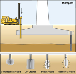
Many deep foundation systems are available for support of wind turbine tower foundations, including driven piles, drilled caissons, augercast piles, and micropiles. Of these systems only micropiles are versatile enough to function either as a new foundation for a planned structure, or as a remedial solution for an existing foundation. Also known as minipiles, pin piles, needle piles or root piles, micropiles can provide exceptional value, particularly in difficult access situations—narrow access or low headroom—or in Karstic geology. Micropiles are available as a design-build service by specialty contractors. Micropiles are relatively small diameter piles (4 to 13 inches) that can be installed in almost any type of ground. Design loads as small as a couple of tons to in excess of 500 tons are achievable. They are generally constructed by drilling either a cased or an open hole in which reinforcing steel and high strength grout are placed.

Micropiles are often an ideal foundation element for wind turbine tower foundations because micropile tension (uplift) capacity is generally a high percentage of the compression capacity. They can be economical alternatives to caissons without compromising on performance. Micropiles are often located around the perimeter of the tower foundation to maximize the micropile capacity to resist the high overturning moments applied to wind turbine foundations. In addition to new tower construction, micropiles are often installed to remediate problems with existing tower foundations, or retrofit existing towers for changes in loading conditions. Micropiles can be installed through holes cored through an existing mat foundation. After installation the micropiles are bonded or mechanically attached to the mat. Alternately, micropiles can be installed around the perimeter of the mat, after which the connection is achieved by enlarging the mat. Although the highest capacity micropiles typically develop their capacity by bonding into bedrock, significant capacities are achievable by bonding into soils. Micropiles are often combined with a variety of grouting or ground treatment to maximize capacities.

These combinations include:
• Compaction grouted micropiles are able to develop loads at shallow depth in loose, sandy soils. Low mobility grout is pumped to expand the base geometry and densify the bearing soil layer.
• Jet grouted micropiles have a high load carrying capacity and are ideal for cohesive soils where the increase in bond surface area increases pile capacity.
• Post-grouted micropiles are suitable for all types of soils. Post grouting enhances the frictional capacity of the soil-pile interface and increases the surface area of the bond zone.
• Pressure-grouted micropiles have a high load carrying capacity in a wide range of soil types, from sands to clayey silt, to fractured rock.

The pile’s frictional bond capacity is enhanced by densification and grout permeation of the surrounding soil, or by consolidation of rock. Quality controls for micropiles can include monitoring grout volumes and pressures during construction of the piles to determine the condition of the subsurface profile as well as the final geometry of the pile. Grout samples taken from production piles during grouting are cast into cylindrical forms for the purpose of laboratory strength testing to verify that the minimum design unconfined compressive strength (UCS) is achieved. Full-scale compression load tests or tension load tests are typically performed on one or more production piles, or on one or more test piles near the proposed micropile locations. Since their initial development over 50 years ago, micropiles have been employed to support every type of structure. Because of their versatility in design and installation, micropiles are an efficient and economical solution for wind turbine foundations.

Specialty Lubricants for Optimum Operation

0

Wind turbines have seen rapid development during the past few years, and lubricants are of particular importance in this context. Lubricants play a vital role in ensuring the components conform to the required operating times. Standard lubricants are often unable to keep up with the ever-increasing performance requirements. This article provides an overview of the specific tribological requirements of wind turbines’ most significant components and the specific tasks to be fulfilled by the lubricants. It shows that the advantages for windmill operators using high-quality specialty lubricants are considerable with regard to reliability, as well as cost-benefit aspects.

Fig. 1

The still young technology of wind power plants benefits from tribologists’ experience and expertise when it comes to lubrication, corrosion protection, and maintenance under taxing conditions. Even in today’s widely used turbines with a power output of 2 to 3 MW, conventional lubricants are pushed to their limits. Turbines designed to generate 5 MW pose conditions simply too harsh for the lubricants described in various international standards, not to mention the 10 MW units already being designed.

Still, the role of lubricants is widely underestimated in the wind energy sector, although it has a decisive influence on the performance, efficiency, maintenance requirements, and service life of the equipment. An additional aspect to consider in wind power stations is that maintenance and repair jobs often have to be carried out under adverse conditions. This problem will be aggravated in the high-capacity offshore wind parks that are going to be built, e.g. when unplanned maintenance becomes necessary during unfavorable weather. If conditions are too harsh, a defective component may even mean that the turbine is forced to remain idle for some time—downtimes of several months are quite conceivable. High-grade lubricants can help prevent such failures and extend maintenance intervals. If just a single inspection is rendered unnecessary, this will more than compensate for the total lubricant costs arising during the entire service life of a plant.

Lubricating Wind Turbines
When choosing a lubricant suitable for a particular wind power plant, the operator has to consider several important factors. Bearing greases, for example, should be easy to pump and allow precise metering in centralized lubricating systems, thereby attaining a good grease distribution. Good wear protection even under vibration increases the bearings’ lifetime during periods of idleness, the so-called “false brinelling” is always a major cause for concern. Also, when the power station runs at low speed, wear is provoked due to the lack of a sufficient hydrodynamic lubricant film. A good lubricant must contain suitable additives to counteract these effects. Finally, it has to be ensured that the lubricant is compatible with the elastomers involved and covers the wide service temperature range of -40 to 300 °F. (With the operating temperature being approx. 190 °F, a service temperature range up to 300 °F results in extended relubrication intervals.).

Different Bearing Requirements
The essential bearings of a wind power plant—main bearing, generator bearing, yaw bearings, and pitch bearings—operate under very different operating conditions and therefore pose very different requirements regarding lubrication. The main bearing rotates slowly but is subject to high loads and vibration. The generator bearing, by contrast, needs to cope with high speeds and high temperatures. Pitch and yaw bearings are subject to high loads as well, but they also perform oscillating motion under strong vibration.

Fig. 2

Due to these varying requirements, wind power plant operators have often had to resort to a variety of greases up to this point. In addition, most wind parks use turbines from more than a single manufacturer, so different lubricant recommendations have to be taken into consideration. And most manufacturers offer various turbine models, which are often used in parallel. For the operator this means that he has to spend a lot of resources on logistics, storage, and grease disposal, plus an increased risk of lubricants being mixed up. Most turbines are still lubricated manually, so service technicians have to carry a variety of lubricants. Another problem is that not all lubricants are available worldwide, at least not in the same quality.

One Grease Solution
Meanwhile, a special-purpose bearing grease for wind power plants has been developed and proven in practice. The individual bearings, with their different requirements, can now be served by a single product without sacrificing lubrication performance. Its wide service temperature range from –40 to 300 °F is a decisive factor for the problem-free operation of wind power plants: As a specification for use in their plants, most manufacturers stipulate -20 °F, so the new grease leaves a sufficient safety margin. The same applies to the upper temperature range, because even in the fast-running generator bearing the maximum temperature is approx. 190 °F. Thanks to this margin, the aging of the grease will be inhibited, relubrication intervals can be extended, and the operator is left with enough flexibility to schedule maintenance to periods of lull. The wide service temperature range from -40 to 300 °F is to be attributed to the special mixture of synthetic and mineral base oils; a product containing only mineral oil would not be able to cope with such temperatures.

Fig. 3

Moreover, the special grease offers good compatibility with all elastomers commonly used for the making of seals. Comprehensive tests have shown that the characteristics of plastic materials, when in contact with this lubricant, change only to a degree that is within the permissible limits. Furthermore, the grease mixes extremely well with other bearing greases, which makes for easier lubricant changeover.

On the whole, this “one grease solution” allows a reduction of unplanned maintenance and downtimes due to bearing damage, leading to a considerable increase in plant productivity. The operator’s repair and spare parts costs can be cut down, as can be the expenses for storage and the disposal of used greases.

Open Gear Drives
Other demanding points to lubricate in wind turbines are the open slew ring and blade pitch gears. While the turbine is running, the lubricant tends to slowly move outward along the tooth flanks, giving way to increasing wear on the teeth and producing stains on the unit when it eventually drops from the gears. For this application a speciality lubricant with a high load-carrying capacity and good adhesion even at very low temperatures is required, which ensures reliable protection against wear and much less staining of the unit.

Gear Oils
As interest in the wind industry grows, engineers are working to improve the efficiency and the output of wind turbines. Gearbox designs contain more equipment designed to produce greater output, and more output means the generation of more heat in the gearbox. As a result, lubricants must function at higher operating loads while helping to reduce temperatures in the gearbox. In addition, plant operators require prolonged oil service life and grease relubrication intervals. The gear oil in a wind turbine is typically changed after as many as 25,000 to 50,000 service hours.

Fig. 4

Today’s widely used commodity gear oils as defined by various standards do not always meet expectations in terms of wear protection, micro-pitting resistance, foam, and residue formation. Gear efficiency is determined to a large extent by the friction characteristics of the lubricating oil. As test rig results show, there are synthetic gear oils that reduce temperatures and power losses considerably compared to standard gear oils. Just to give a few figures: The biggest increase can be realized in gear types that are challenged in normally lower efficiencies such as worm drives. Klüber’s worm gear test rig e.g. runs at approximately 60 percent efficiency with a mineral oil. With a PAO gear oil, efficiency goes up to 70 percent and with a polyglycol oil it rises to 78 percent. As the efficiency increases, the temperature of the gearbox drops. This decrease in temperature increases the life of the gear oil, the seals, and the gearbox as a whole. This may not sound like a big deal if you have one or two gearboxes, but if you have hundreds of gearboxes that energy usage really adds up—even though, in the main gear systems used in wind turbines, the efficiency rate increases attainable are not that high due to the gear type. Tab. 1

Specialty Lubricants
The total cost that can be incurred by failure of a component in a wind turbine—be it a bearing, an open drive, or a gearbox—should not be underestimated. It is not only material and labor costs for replacing the damaged component that have to be taken into account. The time it takes for a new component to be delivered may leave the wind power plant idle for some time, which means that the costs will rise sharply. But costs will actually soar if, for example, due to a damaged generator bearing the rotor and the stator of the generator come into contact, and the generator itself has to be replaced. All this may add up to significant amounts of money. By comparison, the purchasing costs for high-performance lubricants are all but negligible. Furthermore, these specialty products help to substantially improve operational reliability, avoid unplanned downtimes, and increase the efficiency of wind power plants.

A Case for Wind Farm Construction

0

This paper presents a general interest construction topic and introduces the unique techniques used to manage and construct a wind turbine electricity farm that was completed in 2006. Although many construction and management issues associated with other types of construction projects are common to these facilities, the design and construction of a wind power project is relatively new and unique. By gathering information through a series of personnel interviews and job site visits, special coverage is given to the contracting system, foundation design and construction, civil construction, tower and turbine erection, and electrical distribution system. Similar to a case study, the paper also presents difficulties encountered during construction and how these challenges were overcome through continued cooperation, communication, and teamwork by the construction professionals delivering the project.

Introduction
Wind power has been in use for centuries, and it has become the leading mechanically-based source of renewable energy (Dodge, 2006). Since the 1970s large interconnected wind-driven turbines and generators have been constructed in “farms” to generate electricity. Recently these farms have become enormous, using large wind turbines, blades, and towers. While some of the design, management, and construction issues associated with other types of construction projects are common to these facilities, large wind farm construction of a magnitude presented in this paper is relatively new and offers unique challenges.

This paper presents the results of a series of interviews and job site visits to a large wind farm under construction. The objective of the paper is to present a general interest topic to construction educators. Additionally, in a case study format suggested by Kardos and Smith (1979), the paper identifies the challenges encountered on the project and how these challenges were overcome.

Project Overview
The Wild Horse project is owned by a public utility company, and it is located on approximately 9,000 acres of shrub-steppe land about 140 miles east of Seattle, Washington. The project is a 229-megawatt capacity wind-powered electrical generating facility with 127 wind turbines. The generators are connected through underground cables to a central electrical substation, which in turn delivers power to the main power grid. To provide access to each tower, over 32 miles of roads were constructed. Civil construction began in September of 2005, and the 380 million dollar project had 100 percent of the generation capacity commissioned by the end of November 2006.

Project Organization
The project was financed and managed by a public utility company, referred to as the owner in this paper. The utility company provided overall project management from an owner’s perspective, and all of the construction work was contracted to private firms. Fig. 1 shows the major contracts between the owner, prime contractors, and major subcontractors.

Owner: The owner contracted with two major organizations, the tower/turbine supplier, and a developer to manage the majority of the construction contracts. The owner also contracted separately to construct portions of the work that were familiar to the owner, such as power line construction. The owner was also responsible for the major planning of the project, including obtaining a State Environmental Policy Act (SEPA) permit. SEPA is a state policy that requires state and local agencies to consider the likely environmental impacts before approving proposed project. Additionally, the owner provided on-site project management, quality control, and documentation during construction of the project.

Tower/Turbine Supplier: The towers and turbines were designed and manufactured by a firm from Denmark. Towers are made of steel and were constructed in three sections totaling 221 feet in height. They were manufactured in Vietnam, and each tower is topped by a 1.8-megawatt nacelle weighing 75 tons. The nacelle houses the turbine, gearbox, transformers, generator, and mechanical and control devices. Each nacelle is driven by three 129-foot long blades that can vary their pitch and are designed to produce power from wind ranging in velocity from about four mph to a cut-out speed of 25 mph. The tower/turbine supplier subcontracted the erection of the towers, nacelles, blades, and initial commissioning, but was responsible for the final commissioning of these items.

Developer: The owner contracted with a “developer” for most of the construction work. The developer acted as a “Construction Manager (CM) at risk,” with a Guaranteed Maximum Price (GMP), GMP-CM type of contract (Mincks and Johnson, 2004). The title of developer originated because the developer initially proposed the wind farm, but later sold the project to the utility company once it was approved for construction. The contract between the owner and developer was negotiated but the developer used lump-sum bid contracts to buy out the remainder of the construction work. The developer has also become the balance-of-plant contractor, securing a contract with the owner to continue to operate and maintain the wind farm.

Project Construction
Roads and Quarries: The 34-foot wide roadbed was designed and constructed to accommodate the width and weight of a 31-foot wide crane and included a 16-foot wide compacted crushed rock surface for vehicle travel. Because of the size of the cranes, the road design also limited vertical grade, vertical curves, and side slope of the travel surface.

To allow erection of the towers, a crane pad was constructed near each tower site using small dozers. The soil was primarily hard fractured basalt that required ripping, but there were also areas of soft compressible silt that required use of geo-textile fabric. Two on-site quarries were centrally located. Portable crushers were used to produce 1 ¼ inch minus and ¾ inch minus basalt aggregate, which was later used both to make concrete at the mobile concrete batch plant, and as a final surfacing for the roads. With the exception of a portion of the concrete sand, all of the aggregates for the project were provided by the on-site quarries.

Foundations: The towers are supported by a cast-in-place, post-tensioned, two-foot thick concrete “ring” ranging from 25 to 32 feet in length. A drill core sample was taken at the center of each foundation location to aid in the preparation of a geotechnical report. Each tower foundation was located in the field using Global Positioning System (GPS) technology. Since drilling and blasting was required for most foundation locations, a drilling crew drilled the rock to a depth of two feet beyond the design depth of the foundations. Drilling proceeded at the rate of two to three foundations per day, followed by blasting of four to five foundations per day. An excavating crew followed the blasting crew using an extended-boom excavator ranging in size from a Caterpillar (CAT) 320 to a CAT 365. Foundation excavation continued at the rate of one and one-half to two foundation holes per day.

Each tower foundation consists of a post-tensioned high-strength concrete ring formed by two Corrugated Metal Pipe (CMP) forms. The outside CMP is 14 feet in diameter, and the inside CMP is 10 feet in diameter. After excavation, a rough-terrain crane was used to lift and set the outside CMP in the hole. The CMP was then stabilized using concrete gravity blocks and cables and then backfilled on the outside with a 300 psi compressive strength cement-based slurry. Post-tensioning for each concrete foundation “ring” was provided by a “bolt cage” consisting of 120 high-strength bolts. Because the bolts serve as the post-tensioning mechanism, all but the ends of the bolts were encased in a greased sleeve. The cage was assembled in an upright position by a crew who first fitted the tops of the bolts into a steel ring template that matched the bolt pattern in the base of the towers.

The bolt cage was then lifted from the foundation hole by a crane and the bottom steel embedment ring was permanently attached, with a nut on each rod beneath the ring. Next, the inner CMP was lowered into the foundation hole, followed by the bolt cage, as shown in Fig. 2. This assembly was then centered between the two CMPs and cribbed to the proper elevation.

The center of the inside CMP was then backfilled using the foundation excavation spoils. This material served primarily as ballast for the foundation and compaction was not necessary. Next, formwork for a 12-inch thick reinforced concrete floor was constructed on top of the foundation. In a monolithic pour, the concrete foundation ring and tower floor was placed and vibrated, utilizing concrete with a 5,000 psi compressive strength. Approximately 12 of the foundations were located in areas of poor soil and required a square reinforced concrete “collar” four to five feet thick and four feet below grade, as shown in Fig. 3. Tower sections were later bolted to each foundation, with one ring of bolts on the outside and one ring on the inside. Bolts were tensioned in a specified sequence to provide the prestressing force for the concrete foundations and to permanently anchor each tower base section.

Tower, Nacelle, and Blade Erector:
The erector was a U.S.-based firm that subcontracted with the tower/turbine supplier to erect the towers, nacelles, and blades, and to transport these large and heavy items from the port to the job site. The erector also prepared, installed, and pre-commissioned the internal components of each nacelle. The erector used two cranes: a 359-ton wheel-mounted crane, and a 550-ton crawler crane. Additional support equipment such as rough terrain forklifts, small wheel-mounted cranes, and maintenance vehicles were also employed. Prior to beginning work, this contractor had to plan and execute a major mobilization effort that involved 43 tractor-trailer loads of equipment.

Towers, nacelles, and blades were manufactured overseas and transported by ship to Portland, Oregon, where they were unloaded and moved by truck to the site. Once each nacelle was on site, the blade hub, which contains the blade connection points, controllers and bearings, was connected to the nacelle in a marshalling yard, as shown in Fig. 4.

Each tower base section could be set in winds up to 30 mph, while other components could not be set if the wind speed exceeded 22 mph. The upper two sections were initially lifted in a horizontal position. Then, as each section was raised, it was turned upright, using special rigging, and then set on the previous tower section. Tower sections were bolted together from inside the tower. Base and center tower sections were set by the wheel-mounted crane, but the larger crawler crane was used to lift and install the upper tower sections and nacelles. Fig. 5 shows the wheel-mounted crane with the tower base section installed, but installation of the center tower section has been delayed due to high winds.

Electrical Distribution: The main electrical substation for the wind farm was constructed at a location central to a majority of the towers. This substation steps up the incoming power (34,500 volts) from each tower to match voltage in the power grid and is connected to the grid through overhead high-voltage transmission lines. Each wind tower is connected through underground wires to the main substation. To reduce heat buildup due to a combination of the high voltage and high ambient temperature of the site in the summer, the underground power distribution system had to be very carefully designed and constructed. The design called for a deep trench and backfill of bedding sand to ensure heat buildup would not damage the cables or reduce their design life. Additionally, in parallel but separate trenches, fiber optic control and monitoring cables were installed between each tower and the main control building located at the entrance to the wind farm. A large chain trenching machine was used to excavate these trenches, as shown in Fig. 6. All underground splice boxes for these cables were located using GPS technology and recorded on a master as-built set of prints and logs.

Case Study
Project Management Challenges: The contract between the owner and the tower/turbine supplier had an unusual force majeure, or act of God, clause. The contract allowed a maximum of 13 days to be considered in the project schedule as a force majeure delay. This type of clause entitles the contractor to a contract time extension, but not monetary compensation (Collier, 2001). If weather-related delays exceeded the 13-day limit, the contract required the owner to reimburse the contractor for additional expenses incurred. The contract was structured in this manner to share the risk of high wind days that could have potentially caused delays during the tower/turbine erection process.

One of the major challenges of this project from an owner’s perspective was obtaining the SEPA permit. Since most of the towers were located on public land, the owner worked with seven different public agencies to ensure compliance with complex environmental regulations. Additionally, the construction of the wind farm in an environmentally sensitive area, and the effects of transporting large equipment and heavy loads, had to be considered. The owner faced some risk challenges due to the relatively tight schedule, which required completing the project before January 1, 2007 in order to receive favorable tax credits. Also, the relatively remote location and large site resulted in resource delivery and allocation challenges.

The tower/turbine supplier was very successful on this project, primarily because of the seasoned personnel this contractor was able to bring to the project. These people were experienced in wind farm construction, having recently completed a similar project. They also were capable of repairing damaged wind turbine blades on site. Due to their diligence, minimal punch list items were discovered during commissioning. They also hired a wind tower erector who was open to suggestions to increase erection efficiency. Teamwork between the developer’s subcontractors appeared to be a major factor in the success of this project. This spirit of cooperation was prevalent throughout the project, primarily as a result of ongoing communication between all parties involved. Although one of the major subcontractors is normally a competitor to the developer, this competitive spirit fostered efficiencies instead of creating tension.

Project Construction Challenges: The project got off to a slow start in the spring of 2006, due to unusually wet weather. Although located in what is essentially a desert, the area had deep winter snow and underground water that created wet soil problems. This caused a delay in the construction of the roads. The mobilized foundation subcontractor pulled off the site for a few weeks, and the tower erector did not mobilize until later than was originally planned. After favorable weather allowed the soils to dry, construction of the roads proceeded in a timely manner. Other subcontractors were then able to make up lost time by properly managing their crews and equipment.

One of the challenges during foundation construction was avoiding over-excavation for each round foundation in the blasted, basalt rock. Since this was accomplished using large excavators with extended booms, the operators were not able to see the bottom of the holes, and any over-excavation resulted in extra slurry backfill around the outside of the CMP forms. Another challenge was the transportation of the 30-foot long CMP foundation forms. Their large size meant that only two CMP forms could be transported over public highways on one truck. This resulted in 127 deliveries. Another issue that became apparent during the construction process was that the embedment ring located on the bottom of each bolt cage needed to be washed clean of any backfill spoils for the post-tensioning process to work properly.

The erection contractor used a Just-In-Time (JIT) delivery system to maximize production and make use of a limited lay-down area. JIT delivery of components allowed for an efficient production schedule; however when a delay at the site occurred it caused a potential backlog of tower sections, either at the site or on the docks, where the contractor was exposed to extensive site storage charges. The specialized rigging, as shown in Fig. 5, allowed the use of only one crane to lift and tilt the tower sections. This also minimized the effects of wind on lifting equipment. Additionally, work started as early in the day as possible to avoid afternoon winds.

Because of the dispersed location along ridges, the towers were installed in groups based on their location. The erection process consisted of first setting the tower base and center sections using the more mobile wheel-mounted crane. Next, the larger crawler crane hoisted the top tower section, followed by the nacelle and then each of the three blades, before moving to another tower. Due to the crawler crane’s slow travel speed, it was moved from one group of towers to the next during the night. The use of modern and relatively new cranes, combined with a maintenance staff that had ready access to crane replacement parts delivered by air, kept downtimes of the two main lift cranes to a minimum.

The nacelles were extremely heavy and had to be transported to the site on special trucks. Nacelle construction was completed in the field, because the nacelle with the hub and its components attached was too heavy to be transported on public highways. By establishing an on-site marshalling yard and developing an efficient assembly operation, this process did not hamper the progress of the project.
One of the major challenges of building the electrical and control cabling distribution system was excavating in the basalt rock. Basalt is hard and homogeneous, and therefore is a difficult type of rock to excavate. The power distribution subcontractor employed two large Vermeer chain trenchers capable of excavating a two-foot wide trench to a depth of 10 feet. Due to the hardness of the basalt, cutting teeth had to be replaced frequently on these machines, sometimes after only 30 minutes of operation. Because of unanticipated trencher breakdowns, the power distribution subcontractor had to mobilize an additional trencher, and had to work overtime to complete this portion of the project in a timely manner.
Conclusion
The Wild Horse wind farm is a unique and large-scale construction project. The uniqueness is the result of the remote, scattered distribution of the towers, specialized foundations, and large heavy-lift items located in a windy environment. This project required the owner, designers, and contractors to work together and to maintain constant communication and a spirit of cooperation to keep the project on schedule. Risk sharing clauses in the contract, a Just-In-Time delivery system for the major components, experienced personnel, and on-site repair capabilities also contributed to the project’s success. As a result, the project was completed on time to take advantage of tax credits available for this type of power production. It was also very successful from a safety standpoint. With the blasting, deep excavation, and heavy lifting there was the potential for a catastrophic accident, yet the only lost time on the project was the result of limited minor injuries. The owner provided on-site management, daily observation, and quality monitoring, and was very satisfied with the completed project.
Acknowledgments
The authors would like to acknowledge the following members of the construction team that provided data, interviews, access, and allowed an insight into their operations during June, July, and August of 2006: Kim Lane and Brian Doughty from Puget Sound Energy: Mike Burtness, Tom Bensel, and Daniel Long from Utility Services LLC; Michelle Berdusis from Vestas; and Dave Hart from Barnhart Crane and Rigging.
References
1) Collier, K. (2001). Construction Contracts (3rd ed.). New Jersey: Prentice Hall
2) Dodge, D.M. (2006, August 31). Illustrated History of Wind Power Development [WWW document]. URL www.telosnet.com/wind.
3) Kardos G., and Smith C.O., Proceedings of ASEE National Conference on Engineering Case Studies, March 1979.
4) Mincks, W. and Johnson, H. (2004). Construction Jobsite Management, Clifton Park, NJ. Thomson.

Understanding the entitlement process with small wind

0

There are over 25,000 individual planning commissions in the United States, and each has the potential to promote the adoption of regulations hostile to the growth of distributed generation small wind systems. In order to effectively market home and commercial small wind systems, installers need to understand the entitlement process and be able to guide the end customer through this complex process. This requires the installer to first sell the idea of the project to an emotionally committed buyer and then act as a consultant or agent to that buyer, helping them to navigate the planning and zoning process.

If the system will be installed in a rural area on a large piece of land, the process may be simple, involving an application for a building permit and submission of engineering documents. But in many areas arbitrary height limits require expensive and time-consuming variance or conditional use application permit processes, which act as a deterrent to buyers who are on the fence. By providing the service of completing the applications, preparing for and presenting at planning and zoning, city council, or county commissioners meetings, and arranging interconnections, the small wind firm can significantly increase its chances of winning a particular job. Further possibilities exist in providing financing to end users in the form of loans or lease programs, or by carrying the federal tax incentive grants available to commercial customers for installers to add value and increase the likelihood of closing business. I know of one project where the owners had to fight conflicting planning regulations to win approval for their 6 KW system. They set up a crane and suspended a replica of a rotor from it at the exact height of the proposed hub and photographed it from every conceivable angle, all the way around the property. The 50 foot-tall machine was to power an operating organic farm, and the regulations clearly allowed 60-foot structures as part of the agricultural zoning. The images were provided to the consulting installer, who digitally placed the tower into the images and built them into large format presentation boards. When the final public meeting occurred during which the project was to be approved or denied, the boards were brought out to support the contention that the project would have minimal visual impact on the surrounding homes.

The commissioners were swayed, and the project—which until that point had been on shaky ground due to a poorly written zoning regulation that defined a wind turbine as being not more than 35 feet in height—was granted full approval. Without the work and thought put into securing the needed permission, this project would never have happened. After approval was granted the unit was installed and commissioned within two weeks, and it has been providing clean energy to the farm since. By providing additional service the installer can increase sales, the ratio of sales per proposal, and build better businesses around service before the sale, instead of just after it.

Remember to do the following:
• Check HOA regulations, if they limit installations, check local or state law to see if the restrictions can be trumped.
• Offer services covering initial due diligence, application processing, and public meeting support in addition to financing, installation, and maintenance contracts.
• Call planning authorities early, and call them often. Staff often have the best understanding of what’s needed and how to best win approval for projects.
• Don’t underestimate the amount of time involved; use time efficiently, or turn an opportunity into a potentially big loss.
• Pictures are priceless. Use Photoshop sparingly, though. Make it look real so that it’s more believable.

Drive all the way to the finish line. An emotionally committed customer is critical to the success of a project. Once you find one, work hard to support their vision and the rest will fall into place. Don’t give up easily, and view the installation of a small wind system as a right, not a privilege. Be proactive, and make it happen. By providing a complete solution, you make it easier for the end user to become fully engaged in the project.

Making sense of small wind

0

In the small wind industry you will often encounter the sentiment that you should buy the biggest tower you can afford in order to maximize the total energy harvested from the system. This is true, in a sense, and I personally believe that every homeowner with enough space and wind should be allowed to erect as tall a tower as they require to get into good wind, free of the approval processes required in most parts of the country.

Of another mind are the proponents of a new batch of wind turbines designed to harvest wind energy from atop much smaller towers. These are small home-size systems, typically sold on shorter, tilt-up monopole towers, and offering a slew of new technologies designed to harvest energy from previously discounted potential sites such as urban rooftops, commercial centers, or anomalous micro-topographies that allow for the harvest of canyon flows or other natural wind tunnels. I advocate this type of growth in small wind, even though I realize the limitations that short towers and turbulent sites place on any given project’s total production due to certain realities. These include the amount of power available in the wind, and the inefficiencies of the systems converting that power into useful energy.

As an advocate of small wind, I believe that it can truly make a difference, but I also choose to maintain a healthy sense of skepticism whenever I learn of new methods for harvesting wind power. Some seem incredibly outlandish at first, such as the possibility of using roof-mounted turbines. This has actually been studied, and it can be done with vibration and noise remaining within tolerable limits, but energy production will suffer. The energy produced is all that really matters, and each project has a different measure of success, making the classical payback scenario a secondary consideration for some.

In the ideal case, every small wind turbine should be mounted on a tilt-up, monopole, hydraulically-operated tower that is designed to work specifically with the turbine to which it is mated, and the whole rig should be installed and regularly maintained to the manufacturer’s specifications by properly trained and qualified personnel. The turbine owner should have a reasonable expectation of energy production going into the project, as well as a means of assessing actual production in real time once it is commissioned. Most importantly, it should be easier than it now is to obtain zoning approval.

While there are legitimate concerns about safety that drive some of these zoning laws, today’s small wind power systems are safer and more reliable than ever before. As long as the systems are purchased from a reliable manufacturer/representative, and then mounted and maintained by a certified professional, they should continue to provide clean, safe electricity from a free fuel source for decades.

The reality, though, is that there’s a large market demand for personal wind power, even in areas where the ideal is difficult to reach. Do we ignore this segment of the market while steadfastly focusing on the ideal? It gets more challenging when we add to the equation restrictive zoning laws, “not in my backyard”—or NIMBY—property owners, and sometimes-litigious environmental groups. Yet demand continues to rise.

Small wind is here to say, and in the coming years we’ll see it being used in ways and places never before considered. This will be achieved by better blade and equipment designs, R&D efforts, lighter and more-durable materials, and the ingenuity of the professionals who mount, service, and maintain these systems. We will probably see some models that are doomed to failure along the way, but the end result will be improved small-scale power production for residential and other applications.

At present small wind turbines are available from a number of manufacturers, and via widely differing distribution networks. They come in all sizes, and with tower heights ranging from 20 to more than 150 feet. The market is currently hungry for more options, lower costs, and increased reliability, so designers are rushing to fill that demand. In addition to the power independence these systems provide to end users, this situation also offers great opportunity to those capable of dreaming up the next big thing in small wind equipment design. I plan to share more insights into this exciting emerging industry in future installments of this column.

Links in the Wind Supply Chain

0

Current economic conditions, rising energy prices, demand and supply uncertainties, and multiple environmental concerns are driving the United States to rethink its energy portfolio and develop diverse sources of clean, renewable energy. The nation is working toward generating more energy from domestic resources—energy that can be cost-effective and replaced, or “renewed,” without contributing to climate change or major adverse environmental impacts.

After experiencing strong growth in the mid-eighties the U.S. wind industry hit a plateau during the electricity-restructuring period in the nineties, and then regained momentum in 1999. Today the U.S. wind industry is growing rapidly, driven by sustained production tax credits (PTCs), rising concerns about climate change, and renewable portfolio standards (RPS) or goals in roughly 50 percent of the states.

U.S. turbine technology has advanced steadily, offering improved performance. In 2006 alone average turbine size increased by more than 11 percent over the 2005 level to an average size of 1.6 MW. In addition, average capacity factors have improved over 10 percent since 2007. To meet the growing demand for wind energy, U.S. manufacturers have expanded their capacity to produce and assemble the essential components. Despite this growth, U.S. components represent a relatively small share of total turbine and tower materials, and U.S. manufacturers are struggling to keep pace with rising demand (Wiser & Bolinger 2007).

Historical Perspective
The interest in composites for turbine manufacturing has evolved over time. Originally, steel was the main material used, but whenever something with that amount of weight is elevated to such a degree there are risks involved. Trying to find weight-saving solutions became a natural progression. The goals were to make turbines lighter while maintaining and even increasing the strength. Turbine transfer designs originated in Europe, and you’ll find some of the largest wind energy companies headquartered there due to their mature market. Global support for the wind industry development is found in the rising profiles of environmental issues and the vast improvements in the cost to make wind energy viable. The advanced use of composites is a contributing factor in the reduction of equipment cost. The United States began to show increased interest in this market about six years ago and, according to the U.S. Department of Energy’s Energy Efficiency and Renewable Energy Office it installed more new wind energy capacity in 2005 than any other country in the world.

Fig. 1

Depending on the manufacturer, different aspects of a turbine are supplied. Components such as the blades and the cosmetic cover/nacelle of a turbine are parts that typically utilize thermoplastic and thermoset components. Some suppliers to the turbine manufacturers will supply only the parts needed, while others will supply complete assemblies. For instance, McClarin Plastics provides the nacelle housing, nose cone, and spinner hub in addition to value-added assembly work, which consists of installing items such as metal support brackets, electronic components, vents, doors, insulation, and cooling units or heaters into a larger assembly. This assembly work can include as many as 500 part numbers installed into 18 larger component parts, which are then shipped to the turbine OEM. Delivery can be assembled on location, thus decreasing the amount of labor needed. This alleviates the supply chain of ordering and inventorying component parts, which saves time, physical space, and money for the customer.

The Material
Even though metallics (steel and aluminum) are still notable in product design, material systems utilizing composites and plastics have become more prominent. With fiberglass customers found a lighter material offering a comparable lifespan and more cost-effective price tag that better withstood harsh environments. Design and engineering teams are constantly looking at ways to improve manufacturing and performance efficiencies. As the focus shifted to fiberglass, three types of processes took shape: chopper gun, vacuum infusion, and resin transfer molding.

By definition, fiberglass composite (thermoset) is a mixture of resin and glass strands. Manufacturers first used the hand lay-up or chopper gun methods, which incorporated chopped glass in a laminate mat with the resin applied manually. While the composite was lighter than steel, the chopped glass had inconsistent wall thickness and little-to-no structure in the laminate, which led to an unreliable strength reading. This resulted in stress cracks in the composites. The vacuum infusion and resin transfer molding (light) method evolved over time and soon became the industry standard because it allows fiberglass to be designed and purchased in an engineered mat.

In resin transfer molding (light) the resin is injected or drawn into a mold that contains the fibers from a homogenizer under low pressure. The mold can be made from composites for low production cycles or with aluminum or steel for larger production. The difference between composites and metals is better heat transfer with metal, hence quicker cycle times. Metal also lasts longer and deforms less, but maintains a higher cost. The main hurdle with this method is that air can be trapped in the mold, which means a secondary method must be incorporated for allowing this air to escape. Solutions to the problem include extending one level of reinforcement beyond the cavity (with a 25-percent resin loss); appropriate venting; and/or creating a vacuum in the mold (which also improves quality).
Larger structures, better properties (less movement of fibers), increased flexibility of design, and lower costs are some of the advantages resin transfer molding (light) has over compression molding due mainly to the low pressure injection.

Fig. 2

The vacuum-infusion method uses a vacuum operation in conjunction with a custom-made plastic bag that is placed over the laminate. The negative pressure draws the resin through the reinforcement, making it possible to obtain a greater high fiber, high laminate strength. A very near, net-shaped part can be produced, greatly reducing trimming and finishing time operations. Vacuum infusion is the preferred method for very large fiberglass components.

The use of fiberglass has a much higher glass-to-resin ratio that allows for increased strength and the actual structure designed into the laminate gives superior physical properties to a chop mat layout. Now strength can be added where needed while removing material, thus improving the strength-to-weight ratio. Popularity of vacuum infusion and resin transfer molding (light) increased due to four main benefits:

• Allows for a lighter, yet stronger part/product;
• Yields a much higher strength-to-weight ratio;
• Provides easier customization of the laminate that permits controlled thickness variation throughout the part. A manufacturer can build in additional strength only where needed.
• The processes are more environmentally friendly due to being a closed mold process which offers better control of emissions into the atmosphere: the styrene emitted is vented through filters. The chopped/hand lay-up method is an open mold process that emits styrene into the atmosphere.
Today’s technology focuses on the vacuum infusion method and newer resin formulizations. Driving this process change is the push for higher strength tolerance, lighter weight, longer lifespan (today’s turbines have a life expectancy of 20 years), and better costs. McClarin Plastics plays an active role in the process because we’re able to design, fabricate, and test these oversized structures in-house. Our current capabilities enable us to handle parts that reach up to 40 feet in length by 12 feet wide, which are also complex in shape.
Fig. 3
Supplier vs. Partner
When selecting a manufacturer to supply components/parts of a turbine, one must first determine whether it will be a collaborative effort with the company or they will just supply parts. Partners can be viewed as an extension of the team, bringing their set of expertise to the table. Partners can also review the entire design process, identifying opportunities to specifically meet the needs of the project. While a supplier may build to print, a partner can provide a turnkey component. For example, a composite fabricator may supply an assembled nacelle housing, nose cone, and spinner hub; however, inside they can also incorporate hundreds of value-added additional components, which would include items such as electrical, heating/cooling, insulation, controls, vents, doors, etc.

Supplying components is only half the obstacle. Getting them to their destination and ensuring they are still functional on-site provides another level of service found only in partnering. With components the size of a public bus, transportation and field installation servicing can be an added stress. This is especially true when a completed structure is assembled in the field, which is remote at best. A partner may have dedicated contract haulers that can handle oversized, permitted loads as well as offer repair services if a product is damaged in shipping, assembly, or at the wind farm. With partnering it’s the manufacturer’s goal to determine what additional services can be provided that still offer a profit for them, while presenting cost-effective, flexible/easy solutions for the customer.

The Supply Chain
Suppliers/partners should be ISO certified, or working toward certification. Certification guarantees a supplier is capable of providing the necessary documentation to support the requirements of the end user, such as material certifications, process controls, and engineering changes. Even though a supplier is producing only a portion of the whole, it is still their responsibility to ensure all secondary pieces and resin/raw materials purchased for a component are done so to mutually agreed upon specifications and inspected to that set of specifications. Therefore, suppliers must engage in onsite audits and rigorous first product inspection audits with their raw material suppliers. These audits and inspections help ensure the properties, fit, and function of supplied materials will be consistent with every order.

Once materials come in-house, testing should continue. Fiberglass partners must check the weights, viscosity, gel times, etc., to ensure they meet specifications identified and agreed upon at the beginning of the process. For instance, when testing glass the focus is on weights to ensure proper fabric usage.

Fig. 4

An ISO certified supplier will have procedures in place that isolate a faulty piece. JIT (or just in time) purchasers maintain smaller inventories, which sometimes means a slightly higher piece price, but the end result shows a cost savings because JIT suppliers can operate more efficiently, decreasing inventory costs and improving quality.

Due to an ever-increasing global market, some suppliers/partners are required to work internationally because value-added services/parts required by the customer must be European. Those partners who can operate in the global environment understand how to function under the different procedural and ordering requirements dictated by their international vendors. Operating globally adds a new level of expertise, and those who can do so successfully have the advantage of not being bound to domestic supply chains, providing increased flexibility and options for their customers.

A supplier’s/partner’s location can also contribute to a savings of time and money. For example, McClarin’s physical location features multiple sub-contract fabricators within minutes of its headquarters. This close proximity permits us to have our suppliers in-house at a moment’s notice to help solve a problem. In these instances, freight costs are non-existent and turnaround time is almost immediate, both lowering total costs.

Keeping an eye on the big picture when it comes to the supply chain and staying current with where the dollar is, suppliers who operate globally and domestically can identify the most cost effective route for their customers. While today’s market offers value to buy domestically, the possibility exists that the dollar will strengthen and an offshore supply chain would be more economical as we come out of this downturn.

As a nation, we have made much progress in developing our wind resources. Until recently, this industry primarily focused on grid use. However, today’s market includes turbines built in a wide range of sizes and configurations, utilizing a variety of materials. Also, the conversion from metal-to-plastic/composites introduces better costs, in terms of manufacturing, with less field maintenance relating to metals weight and corrosion characteristics. Today, the United States is a prime location for developing wind resources and new wind manufacturing facilities. At the same time, advancing technologies and expanding expertise are producing opportunities to create new methods/processes to meet many of the material needs associated with wind technology manufacturing, installation, and facility operation.

Shifting Political Winds Usher in Opportunities

0

When the American Clean Energy and Security Act was passed by the U.S. House of Representatives in late June, it was trumpeted as one of the biggest legislative victories of President Obama’s administration. It was also viewed as a huge win for the wind and solar industries, which together with a large coalition of supporters and many of America’s largest corporations, lobbied tirelessly for the new legislation. Under the legislation—which experts predict will be confirmed by the U.S.

Senate—electric utilities must secure 20 percent of their electricity demand through renewable energy sources and energy efficiency by 2020. Other key provisions of the bill include: $190 billion in new clean energy technologies and energy efficiency, including energy efficiency and renewable energy, and $90 billion in new investments by 2025; new energy-saving standards for buildings, appliances, and industry; and reduced carbon emissions from major U.S. sources by 17 percent by 2020, and over 80 percent by 2050 compared to 2005 levels.

With an influx of $90 billion in new investments poised to flood the wind and solar power industries within the next 15 years, it’s clear that the need for more cost-effective wind energy solutions is critical. After all, the investment in these industries will mean much more than simply the addition of several thousand wind turbines and solar panels to the American landscape.

So what exactly needs to happen in order for the goals of the American Clean Energy and Security Act to be met? For starters, technology must become more efficient, more dependable, and more effective in order to ease traditional utilities through the transition to renewable energy. My company and many others are already working to develop comprehensive solutions that refine the wind power technology available today. In particular, we are focusing its energy on four key areas of the customer experience: improved performance, enhanced durability, the introduction of scalable technology, and a comprehensive approach.

Improved Performance: Wind turbines usually come with an average $3 million price tag, making a positive return on investment paramount to wind energy producers. So it’s no wonder that wind turbine owners want their systems to run at peak efficiency, with as little downtime as possible. In addition, wind turbines have an average lifespan of 20 years, making it even more critical that they operate at maximum capacity as often as possible.

Progress has been made in this area due to variable-speed turbines that incorporate “smart” pitch and yaw drives. These smart drives are able to optimize harnessed power and prolong the life of wind turbines, thanks to an electronic controller that pinpoints the turbine’s power output several times per second and then calibrates it to the right speed to produce the most energy.

Enhanced Durability: When equipment must constantly operate at peak performance, the durability of individual components becomes a necessity. Preventing failure to wind turbine components—especially rotors, mechanical power train, and electrical generators—requires technology that can keep equipment up and running at all times.

Just as smart yaw and pitch drives can enhance wind turbine performance, they can also improve wind turbine durability and protect turbines from being pushed beyond their limits. This feature is especially helpful when wind gusts exceed 33 miles per hour, the typical speed that wind turbines are equipped to handle. This process allows the wind turbine to create the highest possible power output while maintaining optimal speed, despite high wind conditions. By removing the strain of high winds from the equation, wind farm owners and operators are saved the expense of repairing and/or replacing incapacitated turbines following high winds. This increased durability can also help extend the life of a wind turbine past its average lifetime of 20 years.

Scalable Technology: Twenty years ago, when the first utility-scale wind turbines were installed, they were only accessible to big players in the energy production game. The cost of harnessing wind energy was simply prohibitive to small to medium-sized utilities and plants. But as application engineers in the renewable energy industry have developed and refined new technologies, more cost-effective applications have emerged.

A Comprehensive Approach: The old saying, “The whole is greater than the sum of its parts,” is an ideal way to describe the current approach to wind energy production. We are developing comprehensive wind energy systems that are more reliable, more efficient, and therefore more valuable than the separate components themselves. Buying from a systems provider means that customers are buying the experience and the integrated thinking, not just a single part.

Opportunities for Improvement
Increasing wind turbine performance is just one of several ways the goals of the American Clean Energy and Security Act will be met. A few other key factors the wind power industry must take into consideration during the transition to renewable energy sources include:

• Increasing the lifecycles of wind turbines by manufacturing more simple and reliable internal components;

• Developing a national super grid capable of storing wind energy and delivering it efficiency from the sparsely populated areas where it is gathered to more densely populated areas where it is most needed;

• Helping energy regulators, legislators and energy delivery companies create an atmosphere of cooperation that rewards new and innovative ways to deliver larger amounts of wind-generated energy into the system;

• Mass-producing turbines to reduce their cost below the current price;

• Making the harnessing of wind energy an international priority in which corporations, researchers, and individuals build on each other’s successes;

• Protecting wind power’s position as an environmentally friendly energy option by seizing all opportunities for improvement, and;

• Finding ways to extract more energy from the wind, beyond the 80 percent of the theoretical maximum that most current designs currently obtain.

The Future of Wind Energy
As I’ve mentioned, the next 15 years or so will be especially exciting, as new breakthroughs and new legislation propel wind energy into the mainstream. But without continued innovation, hard work, cooperation, and financial investment the full potential of wind power can never be realized.

Much of that challenge will be met by increasing the performance of wind turbines, by achieving greater dependability of turbine components, improving efficiency and building on recent technological advances—an effort that many of us are already deeply engaged in, and we will continue to invest in. The renewable energy sector as a whole has worked to achieve advances that make wind power viable and the world’s fastest-growing energy source, and it will continue to push the limits of today’s technologies and solutions, making the next generation of equipment even better.

Conversation with Larry Garza III

0

How long have you been involved in the wind industry?

The company has been in business for more than two decades, but we’ve been involved in the wind industry for the past 10 or so years. My background is in the petrochemical and refining industries, and it was immediately apparent to me that our hydraulic tooling for controlled bolt tightening equipment could play an important role in the wind-energy market as well. So we’d already established our reputation and core competency prior to offering our products to wind industry professionals. In fact, if you take everyone here into consideration, we have more than 100 years worth of combined experience. From the very beginning I’ve wanted this company and its employees to be the very best at what we do, and that’s a commitment we renew every day that we come to work. So whether a company is looking for bolting equipment to rent or purchase, or calibration, repair, or field and training services, we’re the company to call.

You seem well diversified, in terms of the markets you serve.

Definitely, and that’s intentional. In addition to the markets I’ve already mentioned, we’re also involved in working with power generating facilities, offshore drilling contractors, in specialty manufacturing, and in heavy industry. While we’ve experienced tremendous growth in our wind-related activities, especially in the past three years, my experience has taught me that it’s not wise to depend too much on one market, or account, because when unexpected economic shifts occur you need other revenue streams to see you through the slump. And even though the wind market is somewhat volatile right now, we see a great deal of potential, especially considering the renewable energy initiatives, projected new wind sites, and building offshore wind farms. So we’re really being proactive in the wind energy sector, and we’re focusing on building longstanding relationships with our customers as they grow.

So many companies entering this market are new, but I would think the fact that you’re well established would play to your advantage.

You’re absolutely right. Whenever you have a relatively young market like wind—here in this country, at least—you’ll have a great many companies of all kinds wanting to get involved and capitalize on the various opportunities. Our level of experience and background is of interest to our present and future clients. They know we have been around for a long time, that we know what we’re doing, and that we’re not going anywhere. Our business relationships are not driven by the lowest price, but by providing quality products and services at any time, and anywhere in the continental United States. The proof that we live up to our commitments is found in the longstanding relationships we have with our existing clients. Once we’ve had the opportunity to prove what we can do, our customers generally call on us again. A great deal of our revenue is generated by repeat business, which is really the best endorsement you can have.

What benefits do hydraulic bolt-tightening tools provide?

Hydraulic tools provide a faster, safer way to break out larger bolts, or those that are frozen, as well as a highly accurate means of tightening them to begin with. It’s critical to insure the integrity of bolts, seals, flanges, and process equipment, and hydraulic tools can really help you to achieve that. As I’ve mentioned, customers can purchase or lease equipment, or we have trained technicians available to either handle the work themselves or train the client’s employees how to do so. The bottom line is that we’re here to help our customers in any way we can, and if we’re convinced we can meet a project’s requirements we proceed with a great deal of confidence based on our many years of experience in demanding industry applications.

For more information: Go to www.aztecbolting.com.