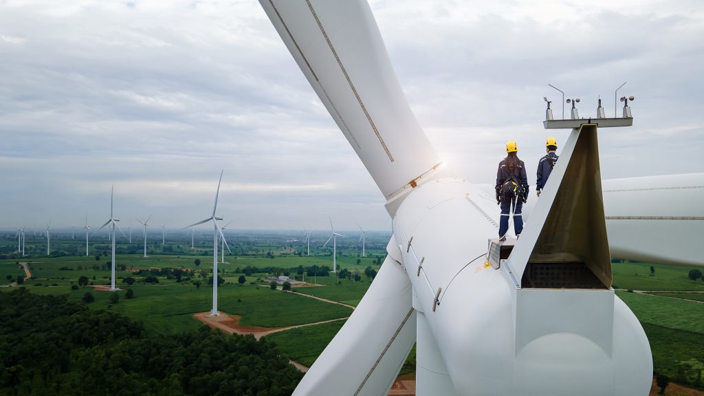
Water droplet erosion (WDE) is the loss of solid material from a surface due to repeated small-scale, high-intensity pressure pulses produced by the impact of high-speed water droplets. Damage from WDE is seen in many applications including steam-turbine blades, aircraft, and missiles, as well as wind-turbine blades. Turbine blades are particularly susceptible to roughening of the surface and loss of material from the leading edge of the blades. Leading edge erosion (LEE), can substantially increase drag force and decrease lift, with as much as a 20-percent decrease in rated power of the turbine. The tips of turbine blades, where the velocity is greatest, have been reported to show LEE damage after as little as two years, and has been the cause of numerous wind installations being taken out of service before their expected end-of-service life.

New materials and manufacturing processes are being developed and applied to reduce the effects of LEE on wind turbines. But there is very little information on their ultimate performance. Accurately predicting their resistance to WDE cannot be done using only their material properties. Controlled testing throughout the development process is critical to selecting materials and manufacturing processes to limit LEE and WDE damage and to predict their success in the field. In this article, the mechanism of the damage, the details of these tests, and their strengths and limitations are discussed.
Predicting WDE Resistance
It is difficult to predict WDE resistance a priori, particularly with new materials and composites that are being developed. Resistance of a material to erosion is not a precisely definable property but is dependent on the interactions of many properties whose importance may depend on the nature, scale, and intensity of the droplet surface interactions. WDE damage to solid surfaces is caused by multiple small, but high-intensity, pressure pulses. The intensity of these impacts depends on the velocity of the droplet relative to the blade, the size of the droplets, and the rate of droplet impacts. The relative velocity of a raindrop with respect to a turbine blade will depend on the speed of the blade, the terminal velocity of the droplet, and the wind speed and direction.
The mass of the rain droplets impacting the surfaces are constrained by the size of the droplets. Typically rain droplets are 1 mm to 2 mm in diameter and rarely exceed 5 mm in diameter, thus their mass is fairly uniform. Rainfall intensity is also a consideration since it affects the rate of droplet impacts that will occur. As turbine blades increase in length and the tip velocities increase, they become more susceptible to erosion. The occurrence of WDE damage is expected to become more prevalent as turbine blade lengths increase, and wind and storm intensities increase.
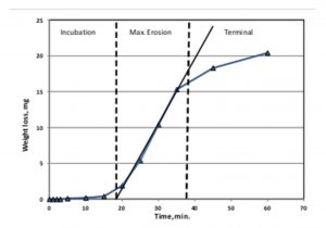
The effects of water droplet impacts are cumulative, and the rate of material loss can vary with exposure time (Figure 1). In the early stages, droplet impacts produce only small surface irregularities with little or no observable loss of material. The solid material absorbs the impact energy and deforms elastically. This incubation phase is marked by little loss of material or performance. However, with repeated erosive forces the material undergoes permanent changes. The incubation period ends with the formation of fractures in brittle materials or the plastic deformation of ductile materials. Fractures will result in intrusion of the liquid into the solid material resulting in deeper fracturing and loss of material. Plastic deformation will generate surface deformations. Ultimately, the surface asperities generated by these processes results in material removal when lateral jets produced by liquid droplet deformation impact them. The effectiveness of a protective coating or surface for delaying LEE can be related to this incubation time and can be used to directly compare different treatment methods and materials.
Once loss of material begins, the rate of erosion can increase rapidly, often increasing until it reaches a maximum, after which some materials show a decrease in erosion rates (Terminal Erosion Stage), while others will not. One theory of why some materials show a reduction in erosion rate is that the surface damage reaches an extent where liquid remains trapped in the crevices and fractures and acts to dampen further fragmentation and loss of material. In controlled testing conditions, the incubation times and maximum erosion rates can be determined from this data and are used to compare materials.
Figure 1 is an example of a sample losing mass with exposure time to water droplet impacts. For this sample, there was little loss of material for the first several minutes (incubation stage). Once the initial surface damage occurred, the observed loss of material accelerated rapidly and reached a nearly constant rate in the maximum erosion stage. As the surface became more deeply eroded, the rate of mass loss began to decrease, and the terminal stage was entered. However, it is not uncommon for materials to show a completely different erosion behavior profile.
Methods of Prediction
Currently, there are two established methods for predicting the effects of WDE on materials: one from the ASTM organization based in the United States, ASTM G73 Standard Test Method for Liquid Impingement Erosion Using Rotating Apparatus, and one from the European Organization DNV, the DNV-RP-0171 Testing of Rotor Blade Erosion Protection Systems and the method for evaluating the damage in those tests, DNV-RP-0573 Evaluation of erosion and delamination for leading edge protection systems of rotor blades.
While both of these tests rotate samples at high speeds so they impact water droplets, there are important differences between them that affect how the tests are run, the results, and interpretation of the results. It is sometimes difficult to compare results between labs unless they are reported in a standardized manner, such as comparing the erosion resistance of a standard material plotted as a function of cumulative impingements in addition to the exposure time.
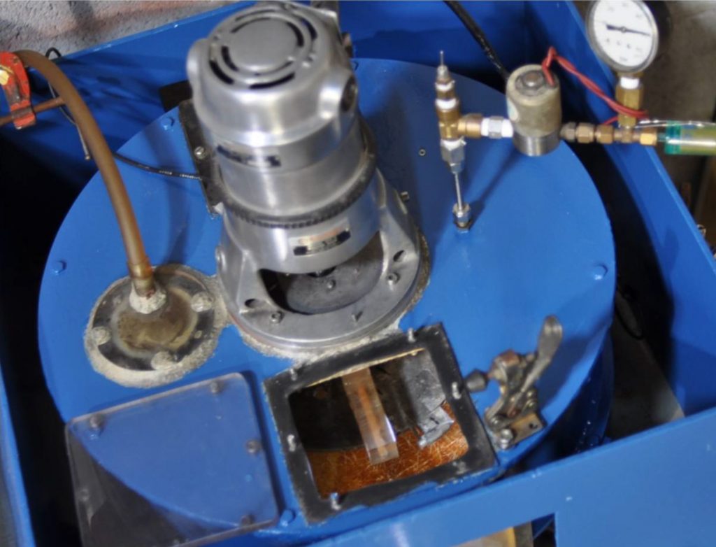
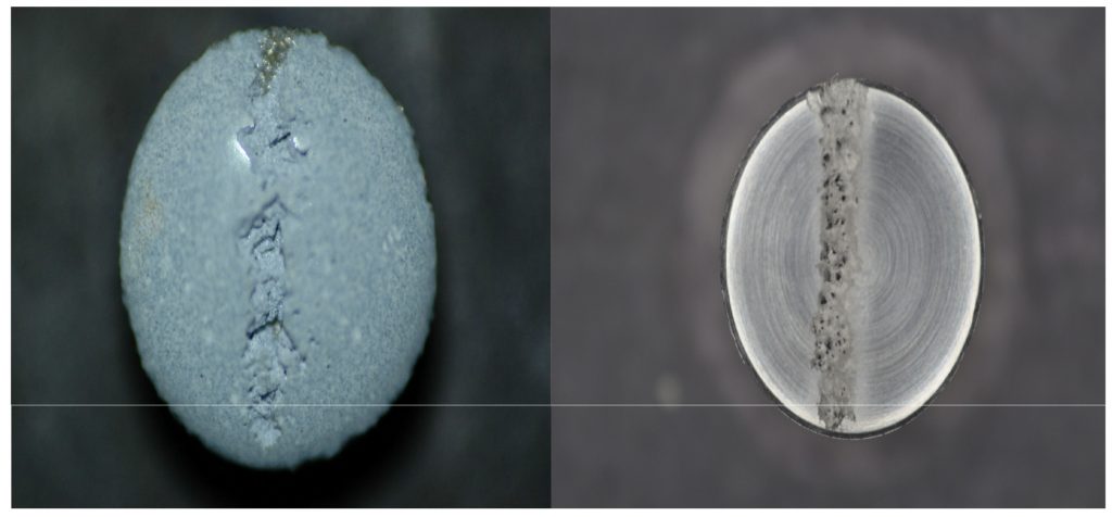
The ASTM G73 method can be used to test not only wind-turbine protection systems, but also metals, elastomers, plastics, composites, and ceramics. In this test, two cylindrical samples with 90-degree flat surfaces of equal mass and dimensions are mounted 180 degrees apart on a solid disc that is rotated at high speeds (Figure 2). The velocity is determined by the length of the radius and the rotation speed of the disc. Water droplets are generated by two water jets supplied by nozzles of known orifice sizes. The water droplets are assumed to be equal to the orifice diameter. The flat surfaces of the sample pieces impact the columns of water. This results in a vertical line of erosion on the faces of the samples. The sample on the left in Figure 3 is an elastomer coated metal and the right-hand image is of a metal sample.
 The tests are often conducted in a chamber under partial vacuum to reduce the temperature variations due to air resistance during testing and to eliminate turbulence in the chamber that can distort the droplet shapes. In typical testing, the samples are exposed to the water droplet impingement for a set length of time, after which, the samples are removed, cleaned, weighed, and photographed. The depths of the eroded areas may also be measured.
Initially, the testing times are relatively short in order to capture the incubation time when there is little weight loss or visible damage to the surface. The incubation time is one of the key results of the test. If a protective coating such as for LEE protection of a wind-turbine blade is being investigated, the incubation time relative to that of an unprotected sample is an indication of its effectiveness. The damage to the surface will first appear as localized pitting with little loss of mass. As the number of impacts encountered by the sample increases, the surface damage becomes more severe, and the loss of material is greater. Often, the rate of erosion will reach a maximum and then begin to decrease. After this point, the erosion rate will decrease and may reach a steady rate. However, for many materials this is not observed, and the mass loss with time plot may not show the curve seen in Figure 1.
Advantages and Disadvantages
The advantages of using ASTM G73 testing include:
- The range of materials that can be tested (elastomers, plastics, metals, composites).
- Higher impact speeds can be obtained.
- Shorter testing times.
- Mass loss data.
- Depth data.
Easier-to-control test parameters such as droplet size, impact speed, and erosion location.
The impact speeds and erosion intensities that can be reached are generally greater than can be achieved using a rotating arm NGV-GL-RP-0171 type test. The disadvantages are that the results may not be directly relatable to predicting wind-turbine protection performance. The ASTM G73 tests can be used to directly compare the erosion resistance of several materials under identical conditions. This information can then be used to select or eliminate materials or manufacturing methods for further development. The NGV-GL-RP-0171 tests can then be used to compare LEE protection of different materials and construction processes.
The NGV-GL 0171 is a whirling arm distributive impact test with testing conditions that are closer to the expected conditions a wind-turbine blade would experience than the ASTM G32 test. However, it is more complex and provides limited data, namely the incubation time to LEE only. NGV-GL-0171 specifies the testing rig in detail. The testing apparatus consists of 1 to 3, 1-meter-long arms that pass through sprayed water droplets.
The droplets can either entirely cover or partially cover the test chamber. It is often difficult to change the droplet sizes or impact speed. The samples are U-shaped 1-meter-long foil shapes with the arc facing the direction of motion. Usually, a 20-centimeter length of the sample is used as the observation region. During testing, the sample arm is not removed between test intervals. This means neither weight changes nor depth of erosion data can be collected until the completion of the test. The damage to the surface is only determined by visual inspection. When observable LEE is detected, the test is stopped.
Ideally these two tests can be used in the selection and development of turbine-protection systems. The ASTM G73 tests would be conducted to select materials and construction methods that exhibit the greatest resistance to droplet erosion damage. The NGV-GL 0171 tests are most useful for estimating the incubation time before LEE damage would be observed. Together, the two types of testing can help the design engineer predict the resistance to LEE that may be experienced during use.


